OPNsense VLAN segmentation: splitting your network into zones
Who this guide is for: IT professionals and home users already running OPNsense who want to split their network into isolated zones. If you are still deciding whether segmentation is worth it, start with the broader home network segmentation guide.
OPNsense VLAN segmentation
Who this guide is for: IT professionals and home users already running OPNsense who want to split their network into isolated zones. If you are still deciding whether segmentation is worth it, start with the broader home network segmentation guide.
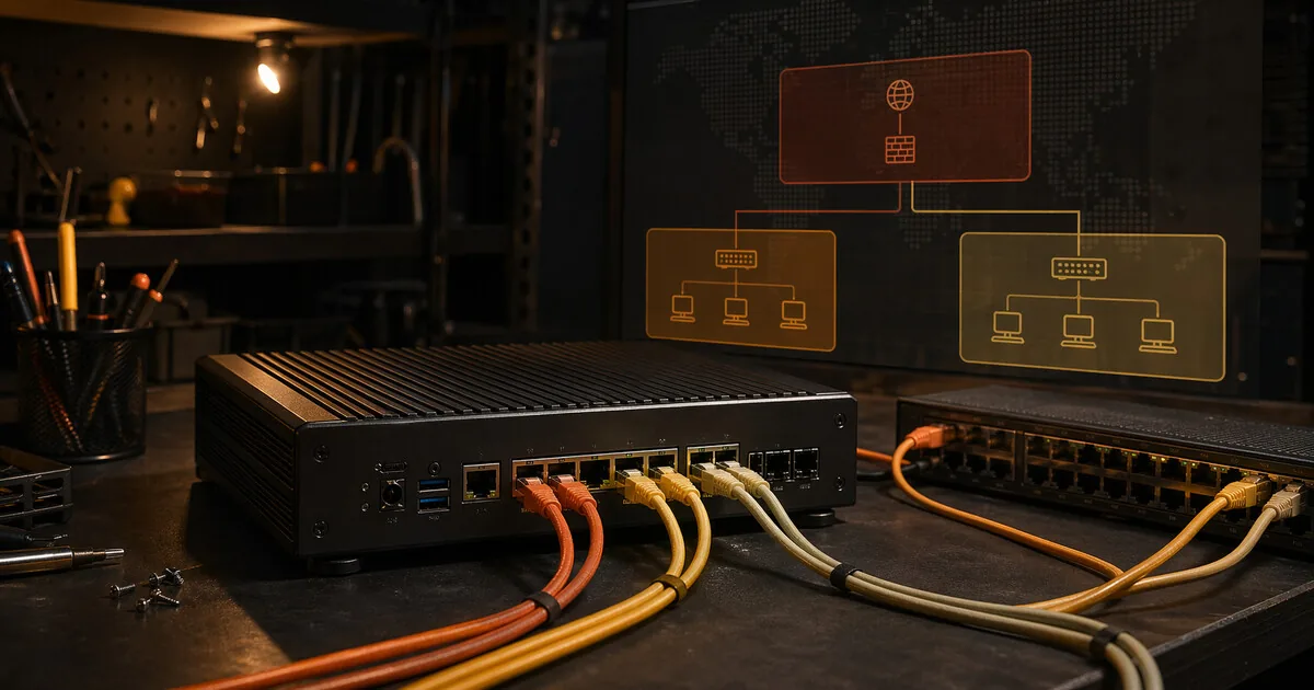
Network segmentation via VLANs divides your home network into logical zones that can’t reach each other. A compromised IoT device then has no access to your NAS or work files.
This article is specifically about OPNsense. Using a GL.iNet router with OpenWrt? See the network segmentation with VLANs guide.
What you gain, and what it costs
You gain fine-grained control over traffic between network zones. With OPNsense, you can separate personal, work, and IoT devices and explicitly decide which zone may or may not reach printers, NAS storage, the internet, or management interfaces.
The cost is that you are now maintaining a real network design. VLANs, firewall rules, switch ports, and access points all need to line up. A small mistake can easily make devices look offline or unexpectedly allow traffic you meant to block.
When this is overkill
If you are not already running OPNsense or only need basic isolation for guests and IoT, start with a guest network or a simpler router setup. This guide only makes sense once you intentionally want an administrator-style network layer and are willing to maintain it.
What you need
- OPNsense running on a Protectli Vault, mini-PC, or virtual machine
- A managed switch supporting 802.1Q VLANs (TP-Link TL-SG108E, Netgear GS308E, or similar)
- An access point that can broadcast multiple SSIDs (most modern APs support this)
Design: three zones
For most home users and home workers, three zones are sufficient:
| Zone | VLAN ID | Subnet | Use |
|---|---|---|---|
| Private | 10 | 192.168.10.0/24 | Laptops, phones, NAS |
| Work | 20 | 192.168.20.0/24 | Work laptop, work phone |
| IoT | 30 | 192.168.30.0/24 | Smart TV, printers, cameras, speakers |
Leave untagged traffic (VLAN 1) for the switch management network.
Step 1 — Create VLANs in OPNsense
Go to Interfaces → Other Types → VLAN.
Click + to add a VLAN:
- Parent interface: the physical interface going to your switch (e.g.
igb1orem1) - VLAN tag: 10
- Description: Private
Repeat for VLAN 20 (Work) and VLAN 30 (IoT).
Step 2 — Assign interfaces
Go to Interfaces → Assignments.
Add the three new VLAN interfaces:
igb1.10→ assign → name itPRIVATEigb1.20→ assign → name itWORKigb1.30→ assign → name itIOT
Then configure each interface:
- Enable: checked
- IPv4 configuration type: Static IPv4
- IPv4 address: the gateway address for that subnet
Example for Private:
- IPv4 address:
192.168.10.1 /24
Repeat for Work (192.168.20.1 /24) and IoT (192.168.30.1 /24).
Save and apply.
Step 3 — Enable DHCP per interface
Go to Services → DHCPv4.
Select each interface and configure:
- Enable: checked
- Range: e.g.
192.168.10.100to192.168.10.200 - DNS servers: leave empty (OPNsense fills in its own IP)
Repeat for all three interfaces.
Step 4 — Configure managed switch
On your managed switch, set per port whether it forwards a VLAN tagged or untagged.
Uplink port (to OPNsense): tagged for all VLANs (10, 20, 30) + untagged for management VLAN 1.
Access ports (for devices): untagged for that zone’s VLAN.
Example for TP-Link TL-SG108E (via web interface):
- Port 1 (uplink to OPNsense): tagged 10, 20, 30
- Ports 2–4 (private devices): untagged 10
- Ports 5–6 (work): untagged 20
- Ports 7–8 (IoT): untagged 30
Also set the PVID (Port VLAN ID) per port to the corresponding VLAN.
Step 5 — Configure access point (multiple SSIDs)
Configure your access point with three SSIDs, each tagged with the correct VLAN:
| SSID | VLAN | Wi-Fi password |
|---|---|---|
| Home_Private | 10 | Strong password |
| Home_Work | 20 | Strong password |
| Home_IoT | 30 | Separate password |
On Unifi: set the VLAN per SSID under Advanced → VLAN ID. On TP-Link EAP: Wireless → SSIDs → VLAN ID.
Step 6 — Set firewall rules
This is the critical part. Without firewall rules, VLANs can still communicate with each other.
Go to Firewall → Rules.
Basic rule per interface: block inter-VLAN traffic
On the WORK interface, add:
- Action: Block
- Interface: WORK
- Protocol: any
- Source: WORK net
- Destination: PRIVATE net
- Description: Block work → private
On the IOT interface, add:
Action: Block
Interface: IOT
Protocol: any
Source: IOT net
Destination: PRIVATE net
Description: Block IoT → private
Action: Block
Interface: IOT
Protocol: any
Source: IOT net
Destination: WORK net
Description: Block IoT → work
Rule: allow internet
On each interface, add (above the block rules):
- Action: Pass
- Interface: [name]
- Protocol: any
- Source: [name] net
- Destination: any
- Description: Allow internet
OPNsense processes rules top to bottom — the “allow internet” rule must be above the blocks for internet access, but the blocks for other VLANs must be more specific (destination = specific subnet).
Alternative: use aliases
Create an alias RFC1918 under Firewall → Aliases with the private subnets 10.0.0.0/8, 172.16.0.0/12, 192.168.0.0/16. Then block on IoT: source = IoT net, destination = RFC1918. This blocks all inter-LAN traffic in a single rule.
Step 7 — Testing
Test isolation: Connect a laptop to the IoT Wi-Fi. Try ping 192.168.10.1 (private gateway) — this must fail.
Try ping 8.8.8.8 — this must work (internet).
Test DHCP: Connect a device to each Wi-Fi network. Verify it gets an IP address in the correct subnet.
Optional: DNS per zone
OPNsense can offer different DNS servers per interface. This lets you run a DNS filter like AdGuard Home or Pi-hole on the IoT interface, while the private zone uses regular DNS.
Go to Services → DHCPv4 → [interface] → enter the DNS server IP.
Next step
Go further
- Tailscale mesh VPN guide — reach this segmented home network safely from outside
- Network segmentation with VLANs at home — OpenWrt/GL.iNet variant
- GL.iNet travel router setup — simpler alternative
Profiles
- Profile: IT professional — context for this level of network control